Aluminum Foil Diaper Makes a Pretty Good Bed Probe
Every 3D printing enthusiast knows that the first layer of a print is the most important. All the subsequent layers are built on top of this one, and its adhesion to the bed is what holds the entire print in place. Modern printers often use bed probes to compensate for slightly warped beds and to achieve a perfect first layer every time.
Many options exist for today's probe shopper. The BLTouch and its clones are very popular. These switches detect the bed via a physical pin. A contactless approach uses an inductive sensor to measure the proximity of a metallic bed underneath. Alternatively, a strain gauge can be employed to detect how forcefully the nozzle is being pushed against the bed. However, if your bed is metal like mine, the simplest solution might just be to wire the bed to one pin on your mainboard and the nozzle to another. When the nozzle touches the bed, the circuit is completed and the microcontroller can accurately detect this.
The bodge
What happens if there is already continuity between the bed and the nozzle? I had been using this probing technique for a long time, but after replacing a plastic piece with the original metal counterpart, I found out the hard way that there is a current path between my bed and nozzle. My printer is a delta and many of the structural pieces are aluminum, so this should not be surprising, but it meant that I would have to come up with an alternative.
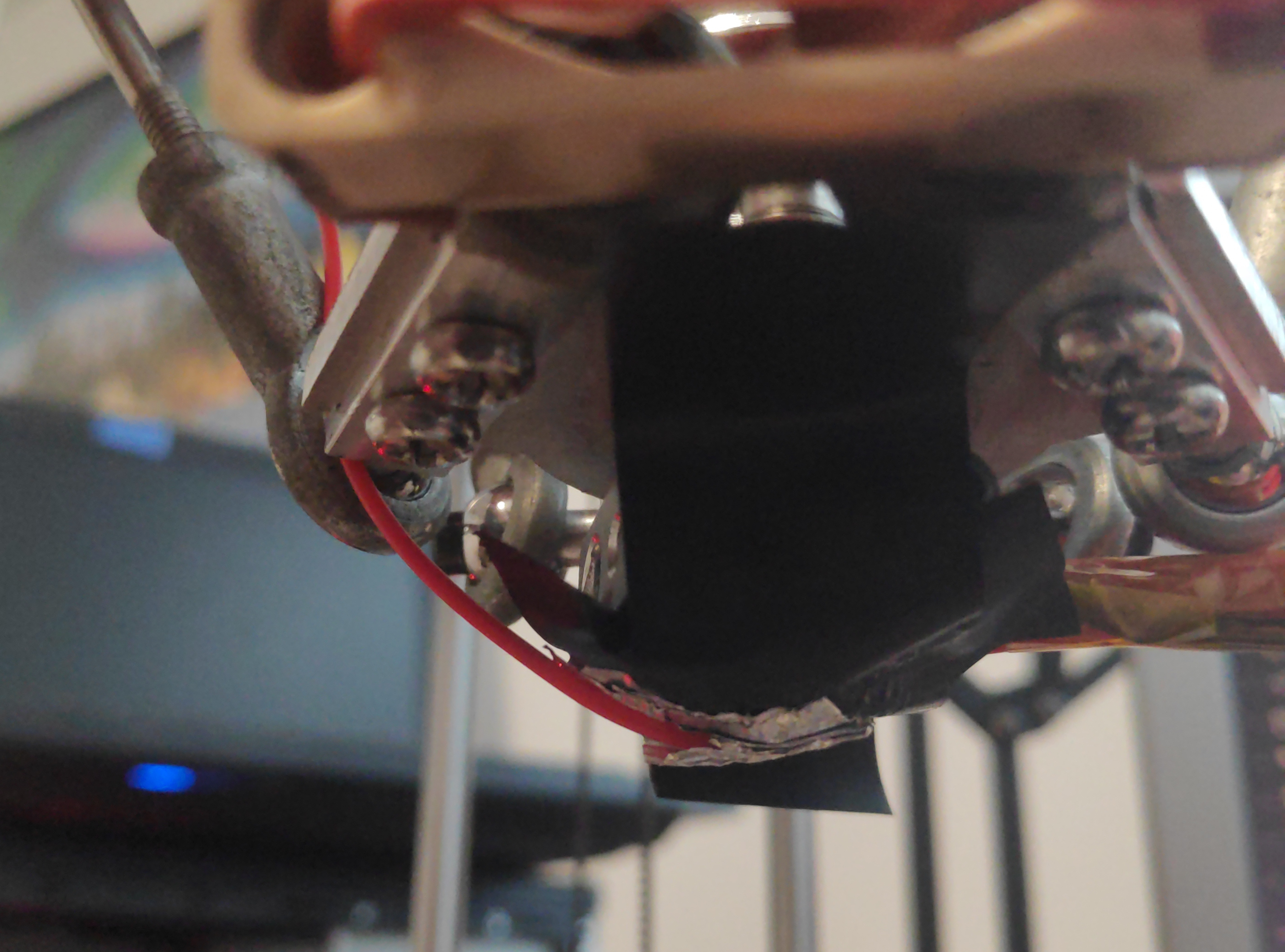
After a few attempts too humiliating to share, I managed to isolate the two components with a bit of electrical tape. Well, the nozzle was still electrically connected, but just below it was an isolated conductive material that I could use to probe my bed! I accomplished this by first isolating my nozzle by liberally applying electrical tape. Then, I constructed a probe by folding a piece of aluminum foil. I stripped the end of a wire and put the exposed side in the crease of the fold, then I used super glue to attach the foil directly underneath my nozzle. The wire went to the pin of the motherboard that had previously been attached to my nozzle.
This bodged probe worked surprisingly well.
I first ran a delta auto calibration by sending G33 to the printer over serial.
This probes many locations in the bed and adjusts several parameters about the printer.
Then, I performed mesh bed levelling,
which probes a grid of even more points
and constructs what is essentially a lookup table of how high the bed is in each location,
compensating for any warp in the bed.
The result is a very nice first layer.

Downsides and upsides
This probe obviously has many downsides. For one, obviously I can't print with this tape and aluminum foil covering my nozzle. Furthermore, my bed is not usually exposed aluminum. When printing, I cover it with blue painter's tape. However, I have found that after calibrating and saving, these settings last for quite some time. The printer homes itself against endstops at the very top.
One advantage of this setup is that the probe is the nozzle. This means that after levelling, the zero position is already nearly perfect (I did dial in the Z offset from the menu). This trait is especially important for delta printers, though. Unless the construction is absolutely perfect, there will be some tiny tilt in the effector as it moves around the bed. If the probe is external to the nozzle (like a BLTouch mounted a few centimeters to the side), then the relative height from the end of this probe to the nozzle will change as the effector moves left to right. While the probe may move parallel to the bed during the first layer, the nozzle will not, which is like the entire point. I have seen delta probes that use a switch temporarily mounted underneath the nozzle, but this has the same problem of separating the probe from the nozzle and is just as cumbersome to set up and take down for calibration.
A final advantage of this particular implementation over the standard "nozzle as probe" complete-the-circuit technique is that you don't have to worry about excess filament isolating the nozzle from the bed. I taped over all of this messiness and applied my own, filament-free conductor.
The setup
In case anyone is interested in such a hack,
using the nozzle as a probe is enabled by the following code snippet in Configuration.h (for Marlin):
/**
 * Use the nozzle as the probe, as with a conductive
 * nozzle system or a piezo-electric smart effector.
 */
#define NOZZLE_AS_PROBE
Connect the bed to ground, and connect the aluminum foil to the Z_MIN signal pin.
This will enable Marlin to recognize the existence of a new Z min probe,
but it won't actually be useful for anything unless you enable some other features
(I guess on non-deltas it could be used to home Z, but you probably already have a way to do this).
Enable delta auto calibration
In order to enable delta auto calibration,
add the following to Configuration.h.
// uncomment to add G33 Delta Auto-Calibration (Enable EEPROM_SETTINGS to store results)
#define DELTA_AUTO_CALIBRATION
As the comment helpfully points out, this will enable the G-code G33 to start a calibration routine.
Once it is done, be sure to save it to the EEPROM with M500.
Enable mesh bed levelling
I use #define AUTO_BED_LEVELING_BILINEAR,
but there are many options for mesh bed levelling in Marlin.
More information about the different options can be found here
and in the comments in Configuration.h in the bed levelling section.
Once it's enabled, you can use G29 to start a mesh bed levelling routing,
but personally I like to use the Bed Level Visualizer plugin for OctoPrint.
This has the added benefit of generating some more advanced G-code
(in addition to G29 it warms up your bed so that the levelling is in the bed's "printing" state, as temperature affects the warp)
and provides a pretty visualizer of the level.

Finally, make sure you actually enable your mesh. Add the following to your start G-code:
M420 S1